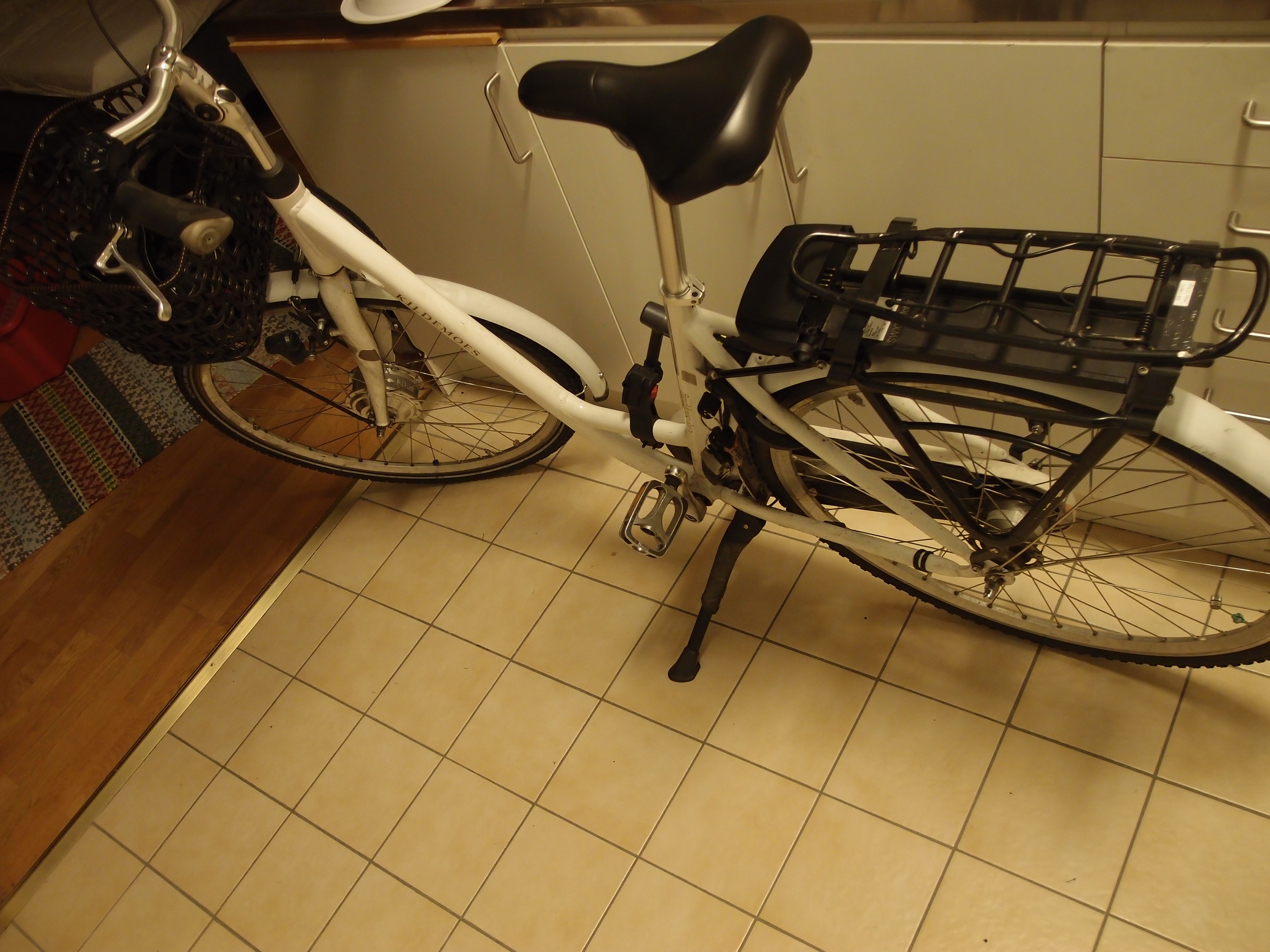
The battery for my electric bike was recently stolen. To try and save some money I've been looking at building a replacement battery from some 18650 cells I have laying around. As part of this I thought I should document my findings on the blog. Hopefully it helps someone. The bike is a Kildemoes City Shopping with an Egoing system.
Note that versions of this post from before 2021-12-21 have VDD on the wrong battery pin. I have also changed the pin order and names to match Phylion's documentation. If you have information from the old version written down/stored then please update it.
Tools needed:
- 3 mm hex driver
- 5 mm hex driver
- PH1 driver
- PH2 driver
Front
The front has the display unit, the motor and a 2.5W LED. The display unit has a USB outlet and three buttonss:
- an on/off button marked ⏻
- a button marked + for increasing power and turning the LED on/off (if held down for a few seconds)
- a button marked - for decreasing power and turning on a "walk mode" which runs the motor at around 5 km/h without having to pedal
The walk mode may technically be illegal under Swedish law unless the bike is considered a "transportation aid" in this mode. It amounts to a throttle, which is not legal to have on a bike. Curiously throttles are legal on vehicles that go no faster than 25 km/h with motor power below 250W if they have no pedals. Perhaps this technicality is useful to someone. Disability aids are allowed any amount of power, and throttles, but are still limited to 25 km/h.
There are seven LEDs on the display. Four LEDs show the amount of energy left in the battery. The remaining three LEDs show the motor power mode. These LEDs can also indicate errors, the meaning of which can be looked up in the manual.
The display is held to the steering bar with a 3 mm hex screw. The hex screw "strap unit" is held to the display with four small PH1 screws. The display unit itself seems to be held together with two PH1 or PH2 screws buried under rubber. Removing the rubber and unscrewing them as far as possible unfortunately does not enable taking the unit apart. It is also not possible to bend the unit apart, at least with the modest amount of force I was willing to use.
Rear
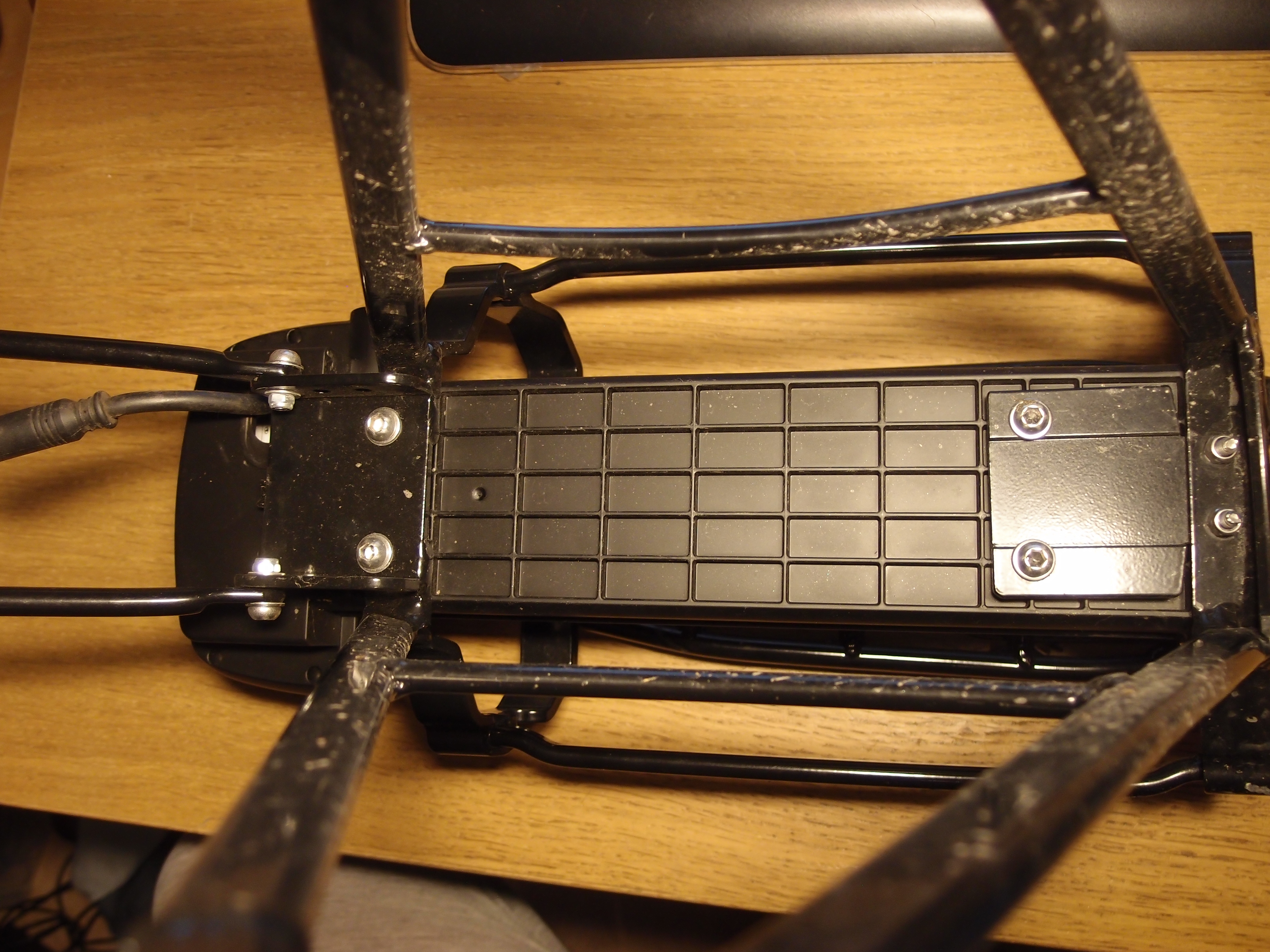
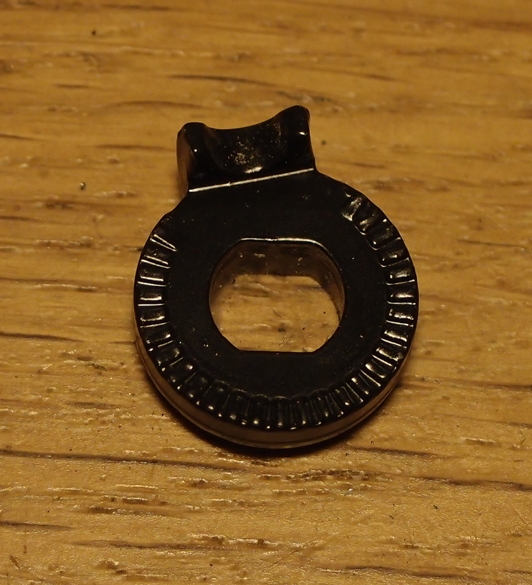
The rear of the bike has a luggage carrier which contains the battery and the ESC. The battery holder and ESC are both part of one plastic unit which I will call the control box. The control box can be removed by unscrewing the four 5 mm hex screws underneath the luggage carrier. To access these screws you need to first remove the luggage carrier, which is also held on with four 5 mm hex screws. Be careful not to mix the screws up, since they all have different lengths. When you remove the control box a 20mm diameter knurled thing will also come loose. I am not sure of the function of this piece.
There are six pins sticking out of the control box. These pins connect to the battery. The leftmost pair of pins are marked "+" and the rightmost pins are marked "-". These correspond to the rightmost and leftpost connectors on the battery. On the floor of the control box, underneath where the battery normally sits, there are some markings. The text "MJXH003" is molded into the plastic and "SWXK Motor" is laser engraved. Between these two markings there is a paper label with the following text:
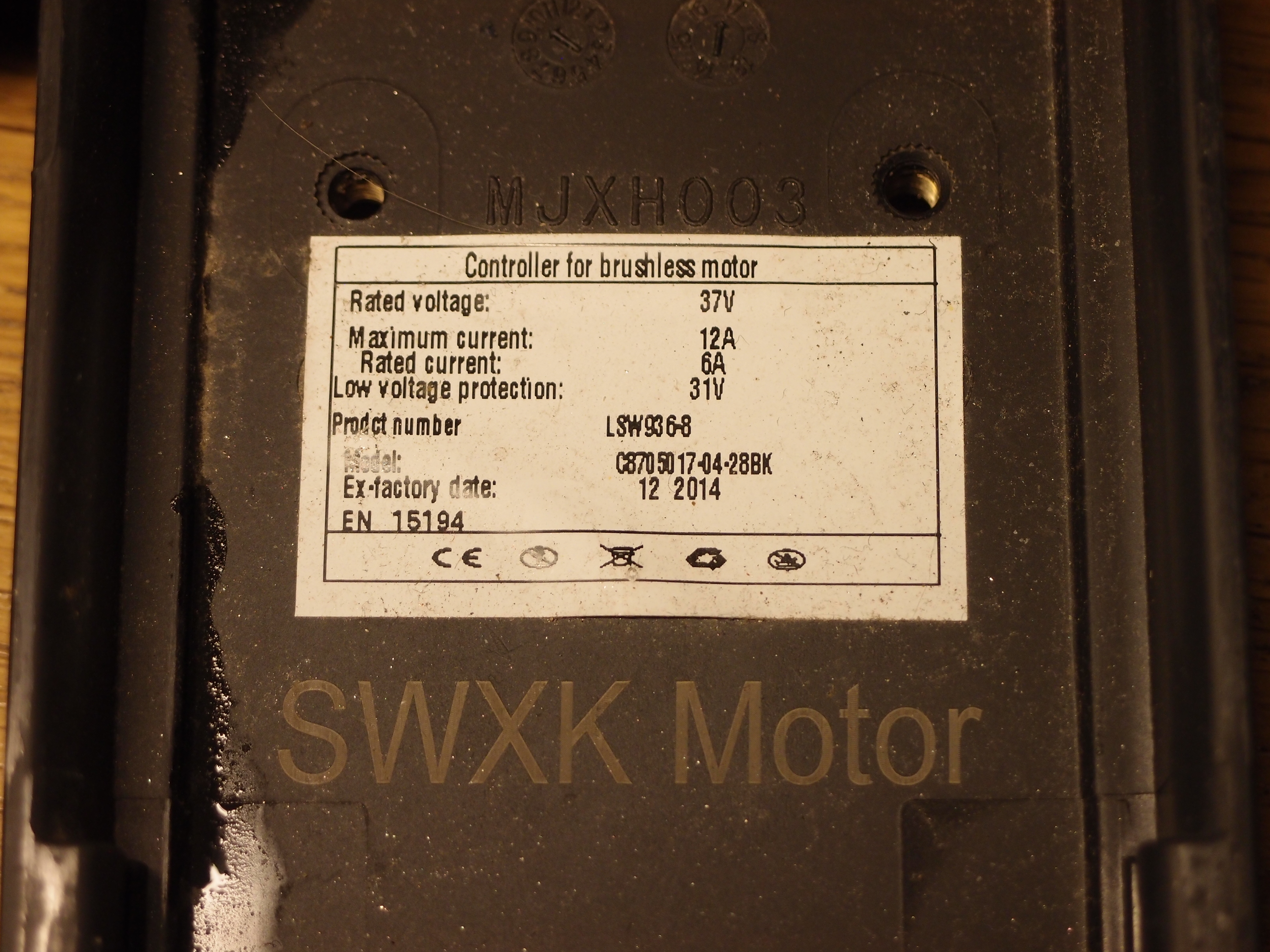
Controller for brushless motor
Rated voltage: 37V
Maximum current: 12A
Rated current: 6A
Low voltage protection: 31V
Product number: LSW936-8
Model: C8705017-04-28BK
Ex-factory date: 12 2014
EN 15194
CE [logos]
While the controller is rated for 37 V, it will accept at least up to 42 V. The quiescent current is 58 mA in my tests and does not seem to depend on the battery voltage. Turning on the light increases current draw to 125 mA at 42 V, 135 mA at 36 V. An error LED will blink if the controller is supplied from a power supply rather than a legitimate battery, meaning the four other pins have some function on this particular controller. More on this later.
The control box is held together with four PH1 screws. Unscrew them and the ESC falls out.
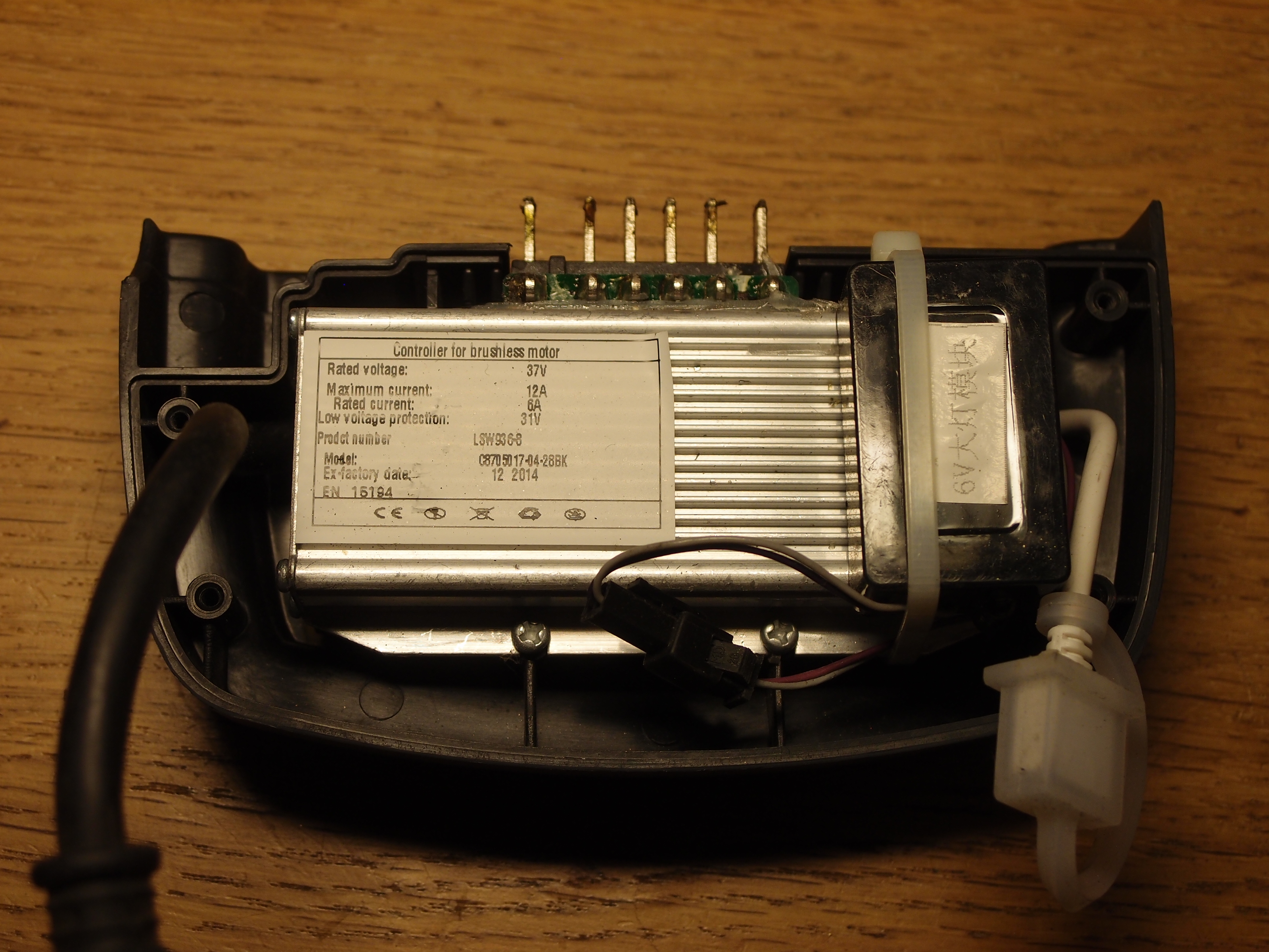
With the ESC oriented so that the text on the label can be read, and the pins sticking up, there is what appears to be a programming connector on the right, attached by a white cable. It has a silicone weather protection cap. On the right there is a box into which four wires enter on one side and two wires on the other. It is marked 6V followed by some chinese writing that I do not understand. Possibly this is a 6V buck converter. If so then I expect a 5V LDO on the board. There are seven TO-220 packages, so it is likely one of them is this LDO and the rest are MOSFETs for driving the motor. The ESC is held in place with two PH2 screws.
Looking on the back of the battery connector, it turns out that it is the leftmost pin that is positive supply and the rightmost pin that is negative, because + and - are molded into the plastic directly behind them, something that is not mechanically possible to do on the front of the connector. The board is conformally coated. The chips on the board have no visible markings. On the leftmost side of the board is what appears to be a current shunt, connected with a thick trace to the negative pin.
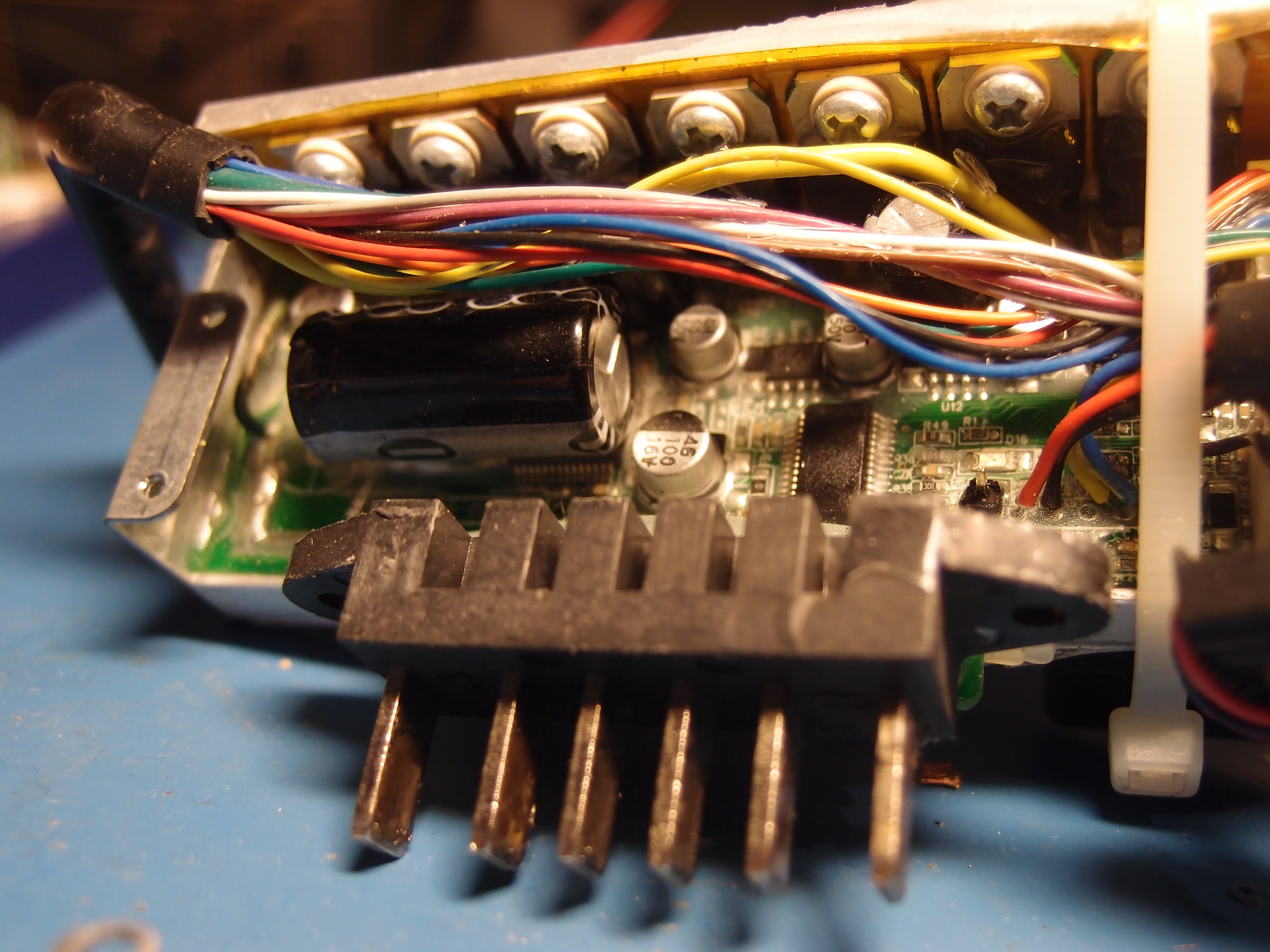
The leftmost TO-220 has no visible markings. The presence of a through-hole bulk capacitor near the first TO-220 supports the theory that this is a regulator. The capacitor measures 1370 µF. There is also a rather large 150 Ohm 0.5% through-hole resistor behind the bulk capacitor (brown-green-brown-[gap]-green).
The other six TO-220's are marked 80NF70, meaning 68V N-channel MOSFETs.
There are two more through-hole electrolytic capacitors on the board, both 100µF 50V.
There are two surface-mount electrolytics marked 100µF 16V and three ones marked 10µF 50V. Next to each of the three 10µF caps are a diode and what I suspect are MOSFET gate driver chips, three of each in total.
The battery is a Phylion Joycube.
Pinout and protocol reverse engineering
The order and names of pins here come from Phylion's documentation. RX/TX are 5V UART at 9600 baud, one start bit, eight data bits, one stop bit. I suspect the battery is a slave device. Either the ESC or the display unit should be the master.
| Pin | Name | Function |
|---|---|---|
| 1 | P+ | Battery positive |
| 2 | VCC | Lights (front and rear) |
| 3 | VDD | +5V (measures +4.75 V). Powers RX/TX optoisolators on battery BMS board. |
| 4 | RX | MOSI. Does not go high immediately. Active after pin 2. Marked "RX" on BMS board. Weakly driven. |
| 5 | TX | MISO. Goes high as soon as the on/off switch is pushed. Active before pin 3. Marked "TX" on BMS board, confirmed MISO via reverse engineering. 560 Ohm to VDD. |
| 6 | P- | Battery negative |
The connector in front of the control box has 13 pins. Three of these pins go to the motor and measure 0.5 Ohm between each pair. The remaining 10 pins go to the display. Of the 10 display pins, 7 connect to the battery pins. Looking at the pin side of the connector, I will be using the following labelling system:

The socket side of the connector is the mirror image of this.
| Circular connector pin | Battery connector pin | Function |
|---|---|---|
| 1 | Unknown | |
| 2 | Unknown | |
| 3 | Unknown | |
| 4 | 1 | P+ |
| 5 | 3 | VDD |
| 6 | 4 | RX |
| 7 | 5 | TX |
| 8 | 2 | VCC |
| 9 | 6 | P- |
| 10 | 6 | P- (yes, connected to pin 9) |
| A | Motor | |
| B | Motor | |
| C | Motor |
The following drawing hopefully makes this more clear:

Again, this is looking at the pin side of the 13-pin connector.
If the 13-pin connector is taken apart while the controller/display is powered on then the quiescent current draw drops from 58 mA to 60 µA. Reconnecting does not bring the display back on, but it does briefly bring the current up to around 100 µA before settling down to 60 µA again. When powered on the system runs fine limited to 60 mA. If the limit is lowered to 50 mA then it dies after a few seconds during which the supply voltage continually drops.
The three pins marked unknown have an as yet unknown function. I suspect one or two of these pins are used for the magnetic sensor on the rear wheel. It might be that some of these pins connect to VDD via some of the switches on the display unit, in particular the power switch. I have not tested this yet.
I have not been able to make any of the display LEDs light up via the 13-pin connector. This and the presence of UART on the 13-pin connector makes me suspect there is a microcontroller in the display. What is not clear is how exactly power on is dealt with. Perhaps one of the pins is an enable pin for the controller, asserted by the display? If so then why does it not seem to connect directly to any supply rail? VDD is not enabled when the bike is off, but P+ is present on the 13-pin connector. Perhaps I measured incorrectly.
Only the UART pins and P- (pins 4 through 6) need to be connected between the battery and the control box. Pin 3 can be supplied from an external 5 V supply. Pin 2 is not necessary. Applying 5 V to it turns on the light, regardless of whether the bike has booted or if P+ is supplied. The light can be turned on from the display unit even with pin 2 not connected to the battery. Pin 1 can be supplied from an external 42 V supply. The UART pins cannot be swapped around.
UART
To sniff UART traffic I have used a USB-to-TTL serial dongle.
Getting it into raw mode requires the following stty incantation: stty -F /dev/ttyUSB0 -echo -icrnl -ixon -onlcr -echoe -echok -echoctl -echoke raw 9600.
First set of runs
These runs were made without a battery connected. The data seen on battery pin 5 (TX) looks as follows:
3A 1A 53 05 00 00 00 21 00 93 00 0D 0A
3A 1A 53 05 00 00 12 21 00 A5 00 0D 0A
3A 1A 53 05 00 00 12 21 00 A5 00 0D 0A
3A 1A 53 05 00 00 12 21 00 A5 00 0D 0A
3A 1A 52 05 00 00 12 49 00 CC 00 0D 0A
3A 1A 52 05 00 00 0D AC 00 2A 01 0D 0A [this line repeats indefinitely]
The data doesn't change between power cycles. Pin 4 (RX) sees the following data:
00 [stray NUL? present in all dumps]
3A 1A 53 07 02 40 01 00 9E 08 7F DC 01 0D 0A
3A 16 0D 01 0B 2F 00 0D 0A
3A 1A 53 07 02 40 01 00 9E 08 7F DC 01 0D 0A
3A 16 0D 01 0B 2F 00 0D 0A
3A 1A 53 07 02 40 01 00 9E 08 7F DC 01 0D 0A
3A 16 0D 01 0B 2F 00 0D 0A
3A 1A 53 07 02 40 01 00 9E 08 7F DC 01 0D 0A
3A 16 0D 01 0B 2F 00 0D 0A
3A 1A 52 02 75 20 03 01 0D 0A [this line repeats indefinitely]
So when the error LED is blinking, TX sees 3A 1A 52 05 00 00 0D AC 00 2A 01 0D 0A, then RX sees 3A 1A 52 02 75 20 03 01 0D 0A a few ms later.
This happens roughly twice per second.
I suspect the data seen here is between the ESC and the display. Since I don't know which of these two is the master device I don't know in which directions the data flows.
Second set of runs
In a second set of runs with a battery connected the following data were observed. TX (pin 5), run #1:
3A 1A 53 05 00 00 00 21 00 93 00 0D 0A
3A 16 0D 02 58 00 7D 00 0D 0A
3A 1A 53 05 00 00 12 21 00 A5 00 0D 0A
3A 16 0D 02 58 00 7D 00 0D 0A
3A 1A 53 05 00 00 12 21 00 A5 00 0D 0A
3A 16 0D 02 58 00 7D 00 0D 0A
3A 1A 53 05 00 00 12 21 00 A5 00 0D 0A
3A 16 0D 02 58 00 7D 00 0D 0A
3A 16 0D 02 58 00 7D 00 0D 0A
3A 16 0D 02 58 00 7D 00 0D 0A
3A 1A 52 05 00 00 0D AC 00 2A 01 0D 0A
[the last two lines repeat indefinitely]
Run #2:
3A 1A 53 05 00 00 00 21 00 93 00 0D 0A
3A 16 0D 02 59 00 7E 00 0D 0A
3A 1A 53 05 00 00 12 21 00 A5 00 0D 0A
3A 16 0D 02 59 00 7E 00 0D 0A
3A 1A 53 05 00 00 12 21 00 A5 00 0D 0A
3A 16 0D 02 59 00 7E 00 0D 0A
3A 1A 53 05 00 00 12 21 00 A5 00 0D 0A
3A 16 0D 02 59 00 7E 00 0D 0A
3A 16 0D 02 59 00 7E 00 0D 0A
3A 16 0D 02 59 00 7E 00 0D 0A
3A 1A 52 05 00 00 0D AC 00 2A 01 0D 0A
[the last two lines repeat indefinitely]
RX (pin 4), both runs:
00
3A 1A 53 07 02 40 01 00 9E 08 7F DC 01 0D 0A
3A 16 0D 01 0B 2F 00 0D 0A
3A 1A 53 07 02 40 01 00 9E 08 7F DC 01 0D 0A
3A 16 0D 01 0B 2F 00 0D 0A
3A 1A 53 07 02 40 01 00 9E 08 7F DC 01 0D 0A
3A 16 0D 01 0B 2F 00 0D 0A
3A 1A 53 07 02 40 01 00 9E 08 7F DC 01 0D 0A
3A 16 0D 01 0B 2F 00 0D 0A
3A 16 0D 01 0B 2F 00 0D 0A
3A 1A 52 02 75 00 E3 00 0D 0A
[the last two lines repeat indefinitely]
A 1k resistor must be inserted between the USB-TTL dongle's RX and pin 4 or else the display will error out, indicating a weak drive. If either pin is disconnected then an error is displayed after a few seconds or two.
Side by side comparisons of both sets of runs
This section is very WIP. TX:
No battery                                  Battery run #1                              Battery run #2
3A 1A 53 05 00 00 00 21 00 93 00 0D 0A      [identical]                       [identical]
                                            3A 16 0D 02 58 00 7D 00 0D 0A     3A 16 0D 02 59 00 7E 00 0D 0A
3A 1A 53 05 00 00 12 21 00 A5 00 0D 0A      [identical]                       [identical]
                                            3A 16 0D 02 58 00 7D 00 0D 0A     3A 16 0D 02 59 00 7E 00 0D 0A
3A 1A 53 05 00 00 12 21 00 A5 00 0D 0A      [identical]                       [identical]
                                            3A 16 0D 02 58 00 7D 00 0D 0A     3A 16 0D 02 59 00 7E 00 0D 0A
3A 1A 53 05 00 00 12 21 00 A5 00 0D 0A      [identical]                       [identical]
                                            3A 16 0D 02 58 00 7D 00 0D 0A     3A 16 0D 02 59 00 7E 00 0D 0A
                                            3A 16 0D 02 58 00 7D 00 0D 0A     3A 16 0D 02 59 00 7E 00 0D 0A
                                            3A 16 0D 02 58 00 7D 00 0D 0A     3A 16 0D 02 59 00 7E 00 0D 0A
3A 1A 52 05 00 00 12 49 00 CC 00 0D 0A
3A 1A 52 05 00 00 0D AC 00 2A 01 0D 0A      [identical]                       [identical]
[the last two lines repeat indefinitely]
There is more data sent when a battery is present. Looking more closely at the data that differs between battery runs:
3A 16 0D 02 58 00 7D 00 0D 0A
3A 16 0D 02 59 00 7E 00 0D 0A
The last two bytes appear to be 16-bit checksums of all bytes but the initial 3A. Specifically byte sums in little endian order:
16 + 0D + 02 + 58 + 00 = 0x007D = 7D 00
16 + 0D + 02 + 59 + 00 = 0x007E = 7E 00
Cutting out the initial 3A, the checksums and CRLF we can simplify TX to this:
No battery                   Battery run #1     Battery run #2
1A 53 05 00 00 00 21 00      [identical]        [identical]
                             16 0D 02 58 00     16 0D 02 59 00
1A 53 05 00 00 12 21 00      [identical]        [identical]
                             16 0D 02 58 00     16 0D 02 59 00
1A 53 05 00 00 12 21 00      [identical]        [identical]
                             16 0D 02 58 00     16 0D 02 59 00
1A 53 05 00 00 12 21 00      [identical]        [identical]
                             16 0D 02 58 00     16 0D 02 59 00
                             16 0D 02 58 00     16 0D 02 59 00
                             16 0D 02 58 00     16 0D 02 59 00
1A 52 05 00 00 12 49 00
1A 52 05 00 00 0D AC 00      [identical]        [identical]
[the last two lines repeat indefinitely]
Since TX here is from the battery's POV, 16 0D 02 XX 00 must be data coming from the battery and 1A 53 05 00 00 00 21 00 comes from the other slave device in the system.
Note the extra 1A 52 05 00 00 12 49 00 transmission in the no-battery run.
Perhaps it tells the display to signal an error?
Or if the ESC is slaved to the display, to refuse to turn the motor?
RX with the same kind of simplification, and stripping the initial NUL:
No battery                         Battery run (both)
1A 53 07 02 40 01 00 9E 08 7F      [identical]
16 0D 01 0B                        [identical]
1A 53 07 02 40 01 00 9E 08 7F      [identical]
16 0D 01 0B                        [identical]
1A 53 07 02 40 01 00 9E 08 7F      [identical]
16 0D 01 0B                        [identical]
1A 53 07 02 40 01 00 9E 08 7F      [identical]
16 0D 01 0B                        [identical]
                                   16 0D 01 0B [same as last line]
1A 52 02 75 20                     1A 52 02 75 00
[last line repeats indefinitely]
We see the 1A and 16 line up nicely with rows in the TX dump, indicating that 16 0D is the address for the battery and 1A 53 to the other device.
So the command being sent to the battery is just 01 0B to which the battery replies 02 XX 00.
Note that the longer messages (3A) 1A 53 07 02 40 01 00 9E 08 7F (DC 01 0D 0A) have enough bytes where the checksum exceeds FF, in this case 0x01DC, verifying that they are indeed 16-bit.
Perhaps the extra 16 0D 01 0B activates the ESC? Unlikely.
As for the repeating data, let's look more closely:
1A 52 02 75 20
1A 52 02 75 00
Only a single bit different.
Perhaps this is what actually tells the system to not run the motor?
Note also the that the address is 1A 52 not 1A 53.
A hack to get the system to work with a custom battery might be to pull the RX bus low for this bit.
This should be easy since the bus is so weakly driven.
Battery
The battery is a Phylion Joycube. It is a 10S4P battery, meaning 36 V nominal, 42 V when fully charged. They come in at least 8.8 Ah (2200 mAh cells) and 11.6 Ah variants (2900 mAh cells). It has a "smart BMS" which I suspect is an anti-competition/anti-third-party-market feature, at least from Crescent's point of view. Phylion likely provides this just as a useful feature.
The battery is held together with six PH2 screws on the bottom and two PH1 screws in the charge port. Some amount of force is required to pull the battery shell apart.
The BMS board contains an STM32 (F072C8T6) and a BMS chip (bq7694003). RX and TX are marked. There are two optoisolators (2501-1), for the RX and TX pins.
There are two pairs of NCE80H12 N-channel MOSFETs (80V 120A). These are driven by a FET driver (bq7620b) on the bottom of the board, connected to the gates to each pair of MOSFETs through 100 Ohm resistors.